
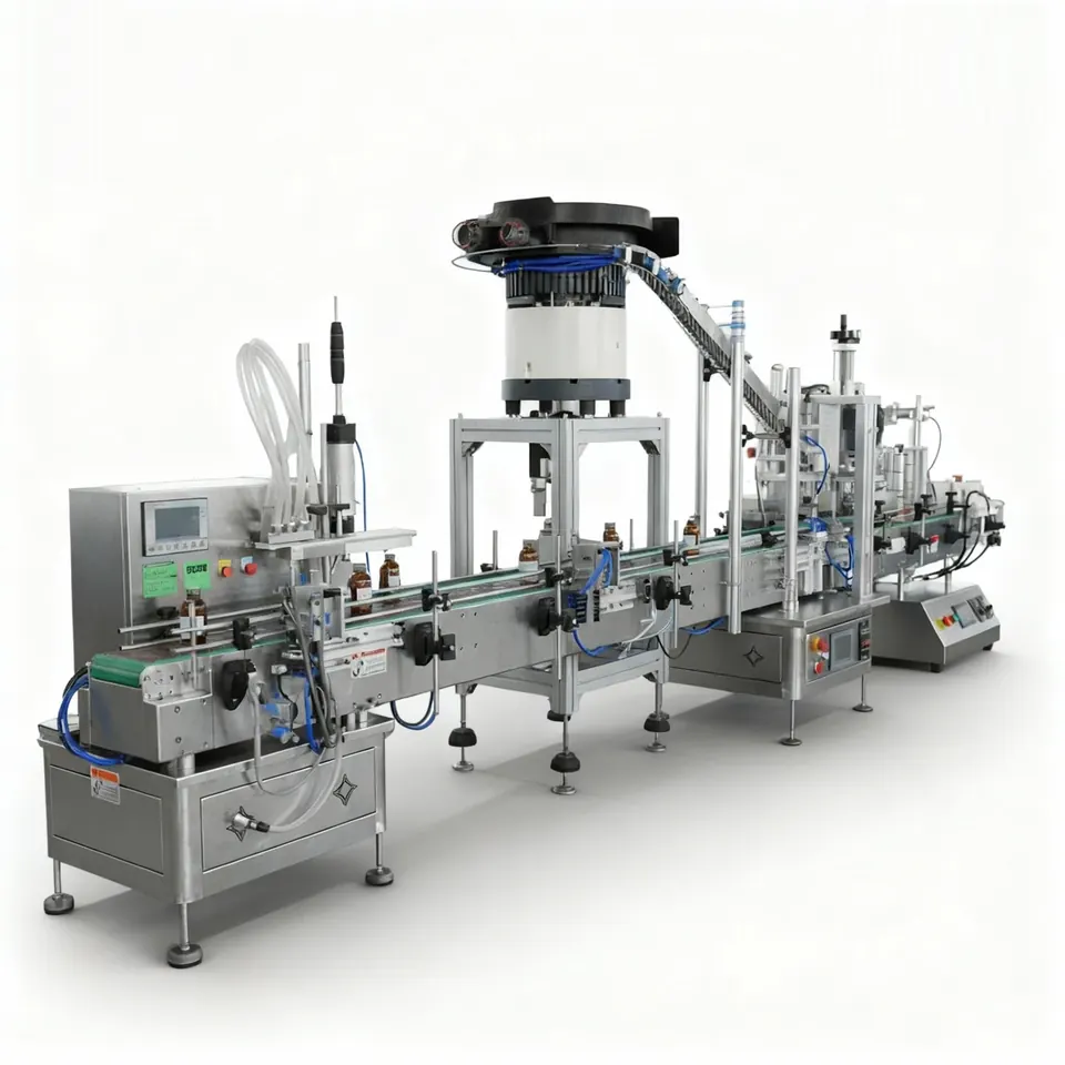
Direct answer
Compare the complete operating envelope, not one nominal speed
- Inline machines normally index or stop containers in one or more rows along a straight conveyor path.
- Rotary machines carry containers around a circular path using stars, platforms or other dedicated handling.
- Container variety, format-part burden and changeover evidence can be as important as peak mechanical rate.
- Product feed, filling time and nozzle behaviour may limit both layouts before container transport becomes the constraint.
- The line must be assessed in blocked, starved, fault and restart states as well as steady running.
How the layouts differ
An inline filler arranges the filling stations beside or above a generally straight container path. Containers may stop beneath a bank of nozzles or index through controlled positions. This can make the process easy to observe and can suit a broad range of automatic and semi-automatic line concepts.
A rotary filler carries containers around a turret or circular transfer. Multiple filling positions can work at different points in the rotation, but the pack-handling system and change parts must be designed around the container range. Rotary does not mean universally faster, and inline does not mean universally more flexible; each claim has to be tested against the full application.
| Decision factor | Inline layout | Rotary layout |
|---|---|---|
| Container path | Generally straight, often using conveyor guides, stops and indexing. | Circular transfer with stars, platforms, clamps or dedicated pitch control. |
| Changeover | May use adjustable guides and recipe changes, with format parts where required. | Often relies more heavily on matched transfer and holding parts for each container family. |
| Observation and access | Stations can be visually open along the line, subject to guarding. | Many stations are arranged around a compact rotating process area. |
| Output potential | Depends on nozzle count, fill time, indexing and downstream acceptance. | Depends on station count, rotation, dwell, transfer and product feed. |
| Best evidence | Trials at the real dose range and pack mix. | Trials plus confirmed change-part and transfer design for each pack family. |
What is an inline filling machine?
An inline filling machine fills containers along a generally straight production path, often using a conveyor, guides, sensors and indexing controls to present one or more packs beneath filling nozzles. Inline layouts range from compact machines to multi-head automatic systems. They can be configured for intermittent or continuous container movement, depending on the dosing method and pack. The useful specification should state nozzle count, indexing sequence, container pitch, accumulation assumptions and the accepted-pack output expected with normal operator work.
What is a rotary filling machine?
A rotary filling machine transfers containers around a circular turret so that several filling stations can operate at defined positions during rotation. The containers are normally controlled by stars, platforms, clamps or guides matched to the pack geometry. Rotary layouts can provide many process positions within a compact machine envelope, but container transfer, product distribution, cleaning access and change parts must all be evaluated. The term “rotary” alone does not establish suitability or accepted output.
Which layout is easier to change between containers?
The easier layout is the one with the fewest controlled, repeatable format changes for the actual container family; this can be inline or rotary depending on the pack geometry and handling design. Compare every item that moves or locates the pack: guides, stops, screws, stars, pucks, nozzle centres, platforms, sensors and recipe values. Ask for a changeover sequence and a list of format parts. A trial with the smallest, largest and least stable packs is more useful than assuming that adjustable rails make a machine fully flexible.
Does a rotary layout always produce more accepted packs?
A rotary layout does not automatically produce more accepted packs because fill time, product feed, foam, settling, closures, inspection, rejects and downstream blocking can constrain the line. Compare sustainable accepted output under defined conditions rather than mechanical container movement alone. Include normal replenishment, changeovers, operator interventions and fault recovery. The output and capacity guide provides a framework for separating cycle rate from saleable production.
How should inline and rotary proposals be compared?
Inline and rotary proposals should be compared against the same product, dose, container matrix, accepted-output definition, utilities, cleaning method, changeover target and integration boundary. Use a common user requirement specification and require each supplier to state assumptions, exclusions, format parts and evidence. A technically mandatory gate should be passed before weighting price or headline speed. Include FAT and SAT criteria for normal running, blocked and starved conditions, stops, faults and controlled restart.
Evidence to request before selecting the layout
- A container and dose matrix covering the minimum, maximum and awkward formats.
- A list of adjustable settings and dedicated format parts for every pack family.
- Sustainable accepted-output assumptions, not only nominal machine speed.
- Product-feed and nozzle evidence at the longest required fill time.
- Changeover steps, access requirements and expected operator tasks.
- Line-state and recovery sequence for upstream starvation and downstream blocking.
Final suitability depends on the real product, pack, environment and integrated process. Use representative samples and agree the acceptance method before the machine design is fixed.